Бренд: CIB Unigas
Категория для инструкций: Горелки газовые
Алфавит (англ.): C
Описание: Гоpелки на сжиженном газе CIB Unigas серии TECNOPRESS: P 60 — P 65, P 72 — P 73 A. Инструкция по монтажу, эксплуатации и техническому обслуживанию.
Размер файла: 4721807 байт
Инструкции на газовые горелки CIB Unigas серии TECNOPRESS
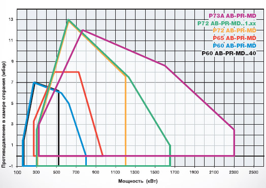
Мощность: 160 — 2300 кВт
ВНИМАНИЕ АКЦИЯ! Скидки до 35% (оставляйте заказ на сайте или пишите в электронную почту!!!)
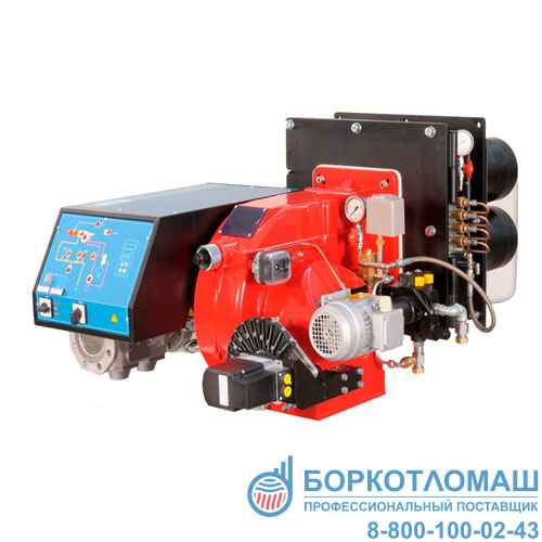
Горелки серии TECNOPRESS, с диапазоном мощностей от 160 до 2300 кВт, могут быть использованы как на теплогенераторах с камерой сгорания под разряжением, так и с аэродинамическим сопротивлением. Колоколообразная головка сгорания в состоянии образовывать пламя рассеянного типа с высокой степенью излучения. Практичные и, в то же время, простые для регулирования и настройки органы горелки, исключительная простота при обслуживании вкупе с превосходным соотношением качество/цена, обеспечивают нашей продукции высокую конкурентоспособность
Cоответствуют ДИРЕКТИВЕ ПО ГАЗУ 90/396/CEE
Для того, чтобы заказать горелку на сжиженном газе, необходимо заменить букву M (метан) на букву L (GPL-
сжиженный газ) и увеличить цену прайс—листа на 5% Пример: P60 L-.AB.S.xx.A.0.50
Для того, чтобы заказать горелку с реле максимального давления газа заменить цифру «0» на цифру «7», в том случае,
если не требуется блок контроля герметичности и увеличить цену на 115 €.
Для того, чтобы заказать горелку с реле максимального давления газа заменить цифру » 1″ на цифру » 8″, в том
случае, если требуется блок контроля герметичности и увеличить цену на 115 €.
Вариант модулирующих горелок (MD) должен быть доукомплектован соответствующимдатчиком модуляции.
ПРАЙС-ЛИСТ в разделе «документы» ниже. Скидки до 35%!!!


| Мощность: | 300 — 1650 кВт |
| Регулирование: | прогрессивное — модулирующее |
| Вид топлива: | природный газ |
| Масса: | 290 кг |
Описание короткопламенной горелки Cib Unigas P72…VS
Короткопламенные газовые горелки итальянской фирмы Cibital Unigas P72 серии TECNOPRESS [300- 2150 кВт] производятся и модернизируются в соответствии с экологическими стандартами и техникой безопасности.
Горелки P72 созданы для использования в котлах с очень короткой камерой сгорания, у которых трубные пучки или стенки котла находятся очень близко к пламяни. Пламя разделено на 4 головы сгорания, за счет чего было достигнуто отличное укорочение длины пламени. Конечно же, характеристики остались прежними.
- вырабатываемая мощность
- модуляция пламени
- соотношение модуляции
- простая наладка
- качественное горение
Регулировка возможна как электронного, так и механического типа.
Комплектация поставки горелки P72...VS
1. Горелка газовая короткопламенная Cib Unigas P72…VS.
2. Паспорт на горелочное устройство.
В связи с постоянным совершенствованием поставляемого оборудования, в его конструкцию могут быть внесены изменения, не отраженные в представленных технических характеристиках. Для получения актуальной информации по оборудованию воспользуйтесь формой обратной связи или позвоните по телефону 8-800-100-02-43 (звонок по России бесплатный).
| Максимальная мощность | 300 — 1650 кВт |
| Масса | 290 кг |
| Электрическое питание | 230/400V 3N ac |
| Двигатель вентилятора | 2,2 кВт |
| Присоединительные размеры по газу | 2” – DN65 – 80 |
В связи с постоянным совершенствованием поставляемого оборудования, в его конструкцию могут быть внесены изменения. Для получения актуальной информации по оборудованию позвоните по телефону 8-800-100-02-43 (звонок по России бесплатный) или воспользуйтесь формой обратной связи
-
Page 1
R1025 R1030 R1040 Gas burners MANUAL OF INSTLLATION — USE — MAINTENANCE BURNERS — BRUCIATORI — BRULERS — BRENNER — QUEMADORES — ГОРЕЛКИ M03996CH Rel. 7.0 06/2010… -
Page 2: Table Of Contents
TABLE OF CONTENTS WARNINGS …………………………..3 PART I: INSTALLATION ……………………….5 GENERAL FEATURES …………………………….. 5 How to interpret the burner’s “Performance curve” ……………………. 6 Burner model identification …………………………..7 Country and usefulness gas categories ……………………….7 Overall dimensions …………………………….8 Performance curves …………………………….
-
Page 3: Warnings
WARNINGS THIS MANUAL IS SUPPLIED AS AN INTEGRAL AND ESSENTIAL PART OF THE PRODUCT AND MUST BE DELIVERED TO THE USER. INFORMATION INCLUDED IN THIS SECTION ARE DEDICATED BOTH TO THE USER AND TO PERSONNEL FOLLOWING PRO- DUCT INSTALLATION AND MAINTENANCE. THE USER WILL FIND FURTHER INFORMATION ABOUT OPERATING AND USE RESTRICTIONS, IN THE SECOND SECTION OF THIS MANUAL.
-
Page 4
DIRECTIVES AND STANDARDS 3b) FIRING WITH GAS, LIGHT OIL OR OTHER FUELS Gas burners GENERAL European directives: The burner shall be installed by qualified personnel and in com- — Directive 2009/142/EC — Gas Appliances; pliance with regulations and provisions in force; wrong installation Directive 2006/95/EC on low voltage;… -
Page 5: Part I: Installation
C.I.B. UNIGAS — M03996CH PART I: INSTALLATION GENERAL FEATURES This series represents monobloc burners made in die-cast aluminium housing with relative flange to work on heating generators. The output range is from 2550kW to 13000kW (according to the burner type). They can be provided in progressive or fully-modulating version.
-
Page 6: How To Interpret The Burner’s «Performance Curve
C.I.B. UNIGAS — M03996CH How to interpret the burner’s “Performance curve” To check if the burner is suitable for the boiler to which it must be installled, the following parameters are needed: furnace input, in kW or kcal/h (kW = kcal/h / 860); backpressure (data are available on the boiler’s ID plate or in the user’s manual).
-
Page 7: Burner Model Identification
C.I.B. UNIGAS — M03996CH Burner model identification Burners are identified by burner type and model. Burner model identification is described as follows. Type R1025 Model (1) BURNER TYPE R1025 — R1030 — R1040 (2) FUEL M — Natural gas (3) OPERATION (Available versions) PR — Progressive MD — Fully modulating (4) BLAST TUBE…
-
Page 8: Overall Dimensions
Overall dimensions (mm) Burner flange and boiler recommended drilling template R1025 1888 1291 680 2142 1320 822 400 450 709 460 1036 200 836 80 1092 216 1146 379 R1025 1888 1291 680 2121 1299 822 400 450 709 714 80 1092 292 1146 379 R1025 1888 1291 680 2123 1301 822 400 450 709…
-
Page 9: Performance Curves
C.I.B. UNIGAS — M03996CH Performance curves R1025 M-..50 R1025 M-..1.xx 2000 3000 4000 5000 6000 7000 2000 3000 4000 5000 6000 7000 8000 9000 R1030 M-..65 R1030 M-..1.xx 2000 3000 4000 5000 6000 7000 8000 9000 10000 2000 3000 4000 5000 6000 7000…
-
Page 10: Pressure In The Network / Gas Rate Curves
C.I.B. UNIGAS — M03996CH Pressure in the network / gas rate curves R1025 M-..50 R1025 M-..1.xx DN65 DN80 DN100 Gas rate Stm Gas rate Stm R1030 M-..65 R1030 M-..1.xx DN80 DN100 1000 1200 1000 Gas rate Stm Gas rate Stm R1040 M-.
-
Page 11: Mounting And Connecting The Burner
C.I.B. UNIGAS — M03996CH MOUNTING AND CONNECTING THE BURNER Packing The burners are despatched in wooden crates whose dimensions are: 2280 x 1730 x 1360 (L x P x H) Packing cases of this type are affected by humidity and are not suitable for stacking. The following are placed in each packing case: burner with gas train detached;…
-
Page 12: Fitting The Burner To The Boiler
C.I.B. UNIGAS — M03996CH Fitting the burner to the boiler To perform the installation, proceed as follows: drill the furnace plateas decribed in paragraph (“Overall dimensions”); place the burner towards the furnace plate: lift and move the burner by means of its eyebolts placed on the top side (see”Lifting and moving the burner”);…
-
Page 13: Gas Train Connections
C.I.B. UNIGAS — M03996CH GAS TRAIN CONNECTIONS The diagrams show the components of the gas train included in the delivery and which must be fitted by the installer.The diagrams are in compliance with the current laws. ATTENTION: BEFORE EXECUTING THE CONNECTIONS TO THE GAS PIPE NETWORK, BE SURE THAT THE MANUAL CUTOFF VALVES ARE CLOSED.
-
Page 14
C.I.B. UNIGAS — M03996CH Gas train 4(DN100/125): Gas train with valves group MBC 1900/3100/5000SE (2 valves + gas filter + pressure governor + pressure switch) + PGCP gas leakage pressure switch and pilot gas train MANUFACTURER INSTALLER Gas train 4(DN100/125): Gas train with valves group VGD40 (2 valves + gas filter + pressure governor + pressure switch) + PGCP gas leakage pressure switch and pilot gas train MANUFACTURER INSTALLER… -
Page 15
C.I.B. UNIGAS — M03996CH The pilot gas train is already installed to the burner, the following connections must be executed: connection from the filter with stabiliser to the gas supply network connection from the valve to the main gas train, by means of the pipe provided with the burner. connection from the pilot gas train to the gas valves group of the main train connection to the gas supply network… -
Page 16: Assembling The Gas Grain
C.I.B. UNIGAS — M03996CH Assembling the gas grain To assemble the main gas train, proceed as follows: gas supply network ”direction” arrows for installation Keys 1A..1E Gasket Gas filter Gas valves group Bellows unit Manual valve Fig. 5 — Example of gas train 1-a) in case of threaded joints: use proper seals according to the gas used;…
-
Page 17: Siemens Vgd20
C.I.B. UNIGAS — M03996CH Siemens VGD20.. and VGD40.. gas valves — with SKP2.. (pressure governor) Mounting When mounting the VGD.. double gas valve, two flanges are required (as for VGD20.. model, the flanges are threaded); to prevent cuttings from falling inside the valve, first fit the flanges to the piping and then clean the associated parts; install the valve;…
-
Page 18: Pressure Adjusting Range
C.I.B. UNIGAS — M03996CH MULTIBLOC DUNGS MBC300-700-1200SE (Threaded valves group) Mounting 1. Mount flange onto tube lines. Use appropriate sealing agent (see Fig. 11) 2. Insert MBC…SE. Note position of O rings (see Fig. 12). 3. Tighten screws A – H Fig.
-
Page 19
C.I.B. UNIGAS — M03996CH Keys 1 spring 2 cap DUNGS MBC valves: Performance range (mbar) 4 — 20 20 — 40 40 — 80 80 — 150 Spring colour black green Siemens VGD valves with SKP actuator : Performance range (mbar) 0 — 22 15 — 120 100 — 250… -
Page 20: Electrical Connections
C.I.B. UNIGAS — M03996CH Electrical connections Respect the basic safety rules. make sure of the connection to the earthing system. do not reverse the phase and neutral connections. fit a differential thermal magnet switch adequate for connection to the mains. ATTENTION: before executing the electrical connections, pay attention to turn the plant’s switch to OFF and be sure that the burner’s main switch is in 0 position (OFF) too.
-
Page 21: Combustion Head Gas Pressure Curves Depending On The Flow Rate
C.I.B. UNIGAS — M03996CH Combustion head gas pressure curves depending on the flow rate Curves are referred to pressure = 0mbar in the combustion head! The curves referred to the gas pressure in the combustion head, depending on the gas flow rate, are referred to the burner properly adjusted (percentage of residual O in the flues as shown in the “Recommended combustion values”…
-
Page 22: Pressure — Rate In Combustion Head Curves
C.I.B. UNIGAS — M03996CH Pressure — rate in combustion head curves R1025 1000 Gas rate Stm R1030 R1040 200 300 400 500 600 700 800 900 1000 1100 1200 1000 1200 1400 Gas rate Stm Gas rate Stm Caution: the gas rate value is quoted on the x-axis, the related network pressure is quoted on the y-axis (pressure value in the combustion chamber is not included).
-
Page 23: Adjusting Air And Gas Flow Rates
C.I.B. UNIGAS — M03996CH ADJUSTING AIR AND GAS FLOW RATES Gas Filter The gas filters remove the dust particles that are present in the gas, and prevent the elements at risk (e.g.: burner valves, counters and regulators) from becoming rapidly blocked. The filter is normally installed upstream from all the control and on-off devices. VPS504 Gas proving system The VPS504 check the operation of the seal of the gas shut off valves.
-
Page 24: Adjusting Air And Gas Flow Rates
C.I.B. UNIGAS — M03996CH Adjusting air and gas flow rates ATTENTION: before starting the burner up, be sure that the manual cutoff valves are open and check that the pres- sure upstream the gas train complies the value quoted on paragraph “Technical specifications”. Be sure that the mains switch is closed.
-
Page 25
C.I.B. UNIGAS — M03996CH The burner is factory-set wih the adjusting plate holes fully open, and the combustion head at its MAX position, so it is fit to work at the maximum output. CAUTION: perform these adjustments once the burner is turned off and cooled. To adjust the gas flow, partially close the holes, as follows: loosen the three V screws that fix the adjusting plate D;… -
Page 26
C.I.B. UNIGAS — M03996CH Start the burner up by means of the thermostat series and wait until the pre-purge time comes to an end and the burner starts up; drive the burner to high flame stage, by means fo the thermostat TAB (for fully-modulating burners set CMF=1 — see paragraph “Fully-modulating burners”). -
Page 27
C.I.B. UNIGAS — M03996CH head position “MIN” head position “MAX” Attention! Change the combustion head position only if necessary. If so, repeat the air and gas adjustments described above. 11 the air and gas rate are now adjusted at the maximum power stage, go on with the point to point adjustement on the SV adjusting cam as to reach the minimum output point. -
Page 28: Calibration Of Air Pressure Switch
C.I.B. UNIGAS — M03996CH Calibration of air pressure switch To calibrate the air pressure switch, proceed as follows: Remove the transparent plastic cap. Once air and gas setting have been accomplished, startup the burner. During the pre-purge phase o the operation, turn slowly the adjusting ring nut VR in the clockwise direction until the burner lockout, then read the value on the pressure switch scale and set it to a value reduced by 15%.
-
Page 29: Part Ii: Operation
C.I.B. UNIGAS — M03996CH PART II: OPERATION LIMITATIONS OF USE THE BURNER IS AN APPLIANCE DESIGNED AND CONSTRUCTED TO OPERATE ONLY AFTER BEING CORRECTLY CON- NECTED TO A HEAT GENERATOR (E.G. BOILER, HOT AIR GENERATOR, FURNACE, ETC.), ANY OTHER USE IS TO BE CONSI- DERED IMPROPER AND THEREFORE DANGEROUS.
-
Page 30: Operation
C.I.B. UNIGAS — M03996CH OPERATION ATTENTION: before starting the burner up, be sure that the manual cutoff valves are open and check that the pres- sure upstream the gas train complies the value quoted on paragraph “Technical specifications”. Turn on the A switch, on the burner control panel. Keys Main switch Lock-out LED…
-
Page 31: Part Iii: Maintenance
C.I.B. UNIGAS — M03996CH PART III: MAINTENANCE At least once a year carry out the maintenance operations listed below. In the case of seasonal servicing, it is recommended to carry out the maintenance at the end of each heating season; in the case of continuous operation the maintenance is carried out every 6 months.
-
Page 32: Replacing The Spring In The Gas Valve Group
C.I.B. UNIGAS — M03996CH Replacing the spring in the gas valve group To replace the spring in the gas valve group,proceed as follows: Carefully twist the protection cap 1 and the O-ring 2. remove the “set value” spring 3 from housing 4. Replace spring 3.
-
Page 33: Adjusting The Ignition Electrode
C.I.B. UNIGAS — M03996CH Adjusting the ignition electrode ATTENTION: avoid the ignition electrode to contact metallic parts (blast tube, head, etc.), otherwise the burner operation would be compromised. Check the electrode position after any intervention on the combustion head. Fig. 17 — Detailed view of the diffuser with pilot (P) and ignition elecctrode (E) Fig.
-
Page 34: Replacing The Ignition Electrode
C.I.B. UNIGAS — M03996CH Replacing the ignition electrode ATTENTION: avoid the ignition electrode to contact metallic parts (blast tube, head, etc.), otherwise the boiler’s operation would be compromised. Check the electrode position after any intervention on the combustion head. To replace the ignition electrode, proceed as follows: remove the burner cover disconnect the electrode (E) cable (CE);…
-
Page 35: Cleaning And Replacing The Detection Photocell
C.I.B. UNIGAS — M03996CH Cleaning and replacing the detection photocell To clean/replace the detection photocell, proceed as follows: Disconnect the system from the electrical power supply. Shut off the gas supply remove the photocell from its slot (see next picture); clean the bulbe if dirty, taking care not to touch it with bare hands;…
-
Page 36: Troubleshooting
C.I.B. UNIGAS — M03996CH TROUBLESHOOTING CAUSE / TROUBLE MAIN SWITCH OPEN LACK OF GAS HIGH GAS PRESSURE SWITCH DEFECTIVE DEFECTIVE THERMOSTAT OVERLOAD TRIPPED LOCK OUT CONTROLS FUSES INTERRUPTED DEFECTIVE AIR PRESSURE SWITCH DEFECTIVE CONTROL BOX DEFECTIVE ACTUATOR AIR PRESSURE SWITCH FAULT OR BAD SETTING GAS PRESSURE SWITCH BAD SETTING IGNITION TRANSFORMER FAULT BUTTERFLY VALVE BAD SETTING…
-
Page 37: Spare Parts
C.I.B. UNIGAS — M03996CH SPARE PARTS Desription Code R1025 R1030 R1040 CONTROL BOX 2020448 2020448 2020448 GAS PROVING SYSTEM — LDU11 2020413 2020413 2020413 PILOT ELECTRODE 2080258 2080258 2080258 GAS FILTER — DN65 2090117 2090117 GAS FILTER — DN80 2090112 2090112 2090112 GAS FILTER — DN100…
-
Page 38: Burners Exploded View
BURNERS EXPLODED VIEW ITEM DESCRIPTION ITEM DESCRIPTION ITEM DESCRIPTION AIR INLET CONE INDEX LABEL 13.2.1 FRONT CONTROL PANEL SPACER AIR DAMPER INDEX 13.2.2 LIGHT BUTTERFLY VALVE ASS.Y GAS PRESSURE 13.2.3 LIGHT PHOTOCELL GAS SOLENOID VALVE 13.2.4 LOCK-OUT RESET BUTTON PLATE GAS GOVERNOR WITH FILTER 13.2.5 PROTECTION…
-
Page 40: Electrical Wiring Diagrams
C.I.B. UNIGAS — M03996CH ELECTRICAL WIRING DIAGRAMS Wiring diagram: Code SE12-059 — Fully-modulating burners Wiring diagram: Code SE12-063 — Progressive burners COMPLETE KEY Fan motor remote contactor coil (line) Fan motor remote contactor coil (star) Fan motor remote contactor coil (delta) Auxiliary fan motor contactor (star) Auxiliary fan motor contactor (triangle) Fan motor contactor (line)
-
Page 53: Appendix
APPENDIX consent to start-up by means of the thermostat or pressostat «R» SIEMENS LFL 1.3.. CONTROL BOX start-up program Automatic programme in the event of interruption and indication of posi- normal burner operation tion when interrupted regulation stop caused by «R» By default, in the event of any kind of interruption, the flow of fuel is imme- programmer returns to start-up position A.
-
Page 54
Ionisation monitor Twin-tube burners (**) voltage in detector electrode Preignition time until the all clear to the pilot burner valve at normal working 330V ±10% terminal 17. test 380V ±10% First safety time (pilot flame strenght); at the end of the safety time short circuit current max. -
Page 55
Programmer diagram pre-ventilation time limit contact switch for damper OPEN position safety time block remote signal ‘1st safety time main relay (working network) with contacts «ar» pre-ignition time Monitor fuse ‘pre-ignition time block relay with «br» contacts interval for creating current between terminals 18 and 19 fuel valve ‘interval for creating current between terminals 17 and 19 reset button… -
Page 60
C.I.B. UNIGAS S.p.A. Via L.Galvani, 9 — 35011 Campodarsego (PD) — ITALY Tel. +39 049 9200944 — Fax +39 049 9200945/9201269 web site: www.cibunigas.it — e-mail: cibunigas@cibunigas.it Note: Specifications and and data subject to change. Errors and omissions excepted.